
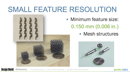
2. Consider small feature resolution
DMLS machines have the ability to image a feature that is as small as 0.006 in. This can be great for certain designs such as mesh structures and sharp features, but it doesn’t mean that all features of a part can be 0.006 in. Because of the rapid heating and cooling that occurs during the process, stress is introduced into the part, which can deform features and then potentially cause them to fail.
For example, these five 2-in. tall plates were created at varying thicknesses, with the thinnest at 0.006 in. or about 0.15 millimeters. The part on the right was about a quarter of an inch high before it started to move. At that point, the remaining layers had nothing to attach to and were swept away by coating action that happens for every layer. The next size part was about 0.010 in. or 0.25 millimeters. It made it a little bit longer, but also failed before it reached its desired height. The 1 millimeter part was the only that finished without any sort of warpage. A general rule is that a free-standing feature should have a 40 to one ratio for heights of wall thickness.
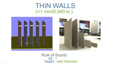
A good design tip would be to eliminate free standing features by creating bracing structures on the edges.

Thanks for making such a cool post which is really very well written.
Wow! Wonderful. Great Great Great Post. Thank You LESLIE LANGNAU .Thank you very much